14/4/2026
Risk Mechanisms, Verification Approaches, and the Importance of ASTM E2336 and UL 2221
Commercial kitchens are among the most challenging areas in a building from a fire-risk perspective due to high heat input, frequent ignition sources, and the continuous generation of grease vapours. Although the fire often starts at cooking equipment, the critical factor that shapes the consequences is frequently what happens along the kitchen exhaust route. Grease exhaust duct (kitchen exhaust duct) systems can accumulate combustible grease deposits over time; they may also run long distances and often pass through shafts or multi-storey routes. Therefore, duct runs that are not designed, protected, and maintained with a system approach can unintentionally become a “transfer path” that carries fire and heat beyond the kitchen compartment.
In projects where fire resistance is required, fire-resistive insulation solutions are preferred along the grease exhaust duct route. However, the reliability of these solutions—especially at penetrations, hanger/support details, and service access points—must be demonstrated through testing. ASTM E2336 and UL 2221 are two commonly used reference standards for evaluating the performance of grease exhaust duct systems under specified fire exposures.
Grease exhaust duct: A fire pathway that amplifies consequences
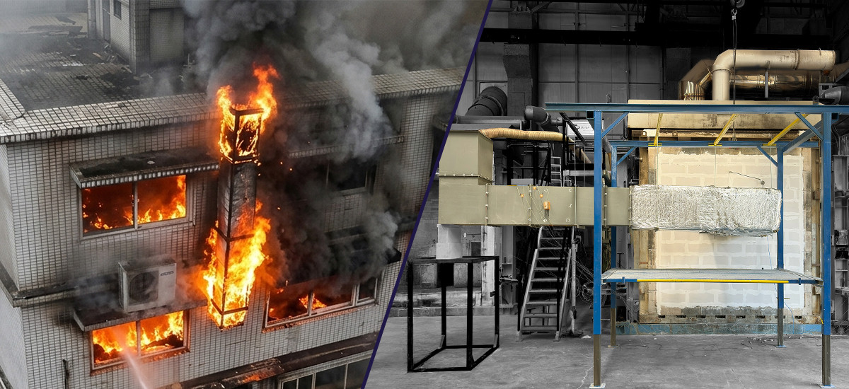
Two fire scenarios are decisive in grease exhaust duct engineering:
- Internal duct fire (grease fire): ignition of grease deposits and flame spread inside the duct.
- External fire exposure to the duct: a compartment fire engulfing the duct route from outside in spaces such as shafts, suspended ceilings, and service voids.
In both scenarios, the objective is the same: to preserve compartmentation and prevent the fire from spreading to a remote location away from the kitchen. Because the duct route includes elbows, joints, service access points, and transitions (penetrations), real performance is determined not by a single material property but by the system’s holistic in-service behaviour. Testing the system as an assembly—including all installation components—is therefore a critical parameter for demonstrating how closely the on-site installation matches the tested/verified configuration.
ASTM E2336 and UL 2221: System-Based Verification of Grease Exhaust Duct Fire Performance
ASTM E2336 and UL 2221 serve essentially the same purpose in practice. They verify the performance of all materials used for grease exhaust ducts as a system/assembly. The assessment does not focus only on the material; joints, hanger/supports, connections, and penetration details are also considered part of the system.
In both standards, the fundamental fire scenarios are similar. The first is the internal duct fire (grease fire) scenario. The second is the external fire exposure scenario (external influence from spaces such as shafts or suspended ceilings). After the fire exposure, the “hose stream” step is used to challenge the system integrity and the robustness of critical details.
On the material side, noncombustibility/combustibility expectations are addressed within a common framework. Typically, noncombustibility in accordance with ASTM E136 is required. In addition, flame spread and smoke development are limited based on ASTM E84 / UL 723.
Scope of Fire Resistance Tests:
The tests are carried out on a grease exhaust duct specimen protected with insulation material. The specimen is prepared to represent field application, and the installation is performed in accordance with the manufacturer/sponsor’s instructions. The report also defines critical details such as the support/hanger system and (if applicable) access/cleaning doors. The external fire test setup simulates the duct passing through a floor slab from inside the furnace and exiting to the outside.
Thermal exposure (internal fire):
In the internal fire test, the duct internal temperature is increased in a controlled manner using gas burners in the test furnace. The internal temperature is increased to at least 500°F (260°C) within 15 minutes and maintained at this level for at least 4 hours. Subsequently, within 15 minutes after the end of the 4-hour period, the internal temperature is increased to at least 2000°F (1093°C) and maintained for 30 minutes.
Measurements and acceptance criteria:
Four thermocouples are used inside the duct for measuring the internal temperature. Temperature increase on the external (unexposed) surface is monitored using at least 16 surface thermocouples placed at locations representing the most adverse heat transmission (including surfaces, joints, support/hanger contact points, and around the access door).
Acceptance criteria are based on limits such as: during the 500°F phase, the temperature rise at any external surface thermocouple shall not exceed 117°F (65°C); during the 2000°F phase, the average temperature rise of external surface thermocouples shall not exceed 250°F (139°C), and no individual thermocouple shall exceed 325°F (181°C). In addition, integrity criteria are evaluated, including the external insulation system remaining in place, no openings/voids forming, and no sustained flaming on the unexposed side (except for limited exceptions defined in the standard).
The external fire test is applied to a separate duct specimen. In this stage, the setup is tested in a horizontal furnace in accordance with the ASTM E119 time–temperature curve for the duration specified by the sponsor; measurement and evaluation are carried out on the basis of ASTM E119 and ASTM E814, and the specimen is subsequently subjected to a hose stream. At this stage, no openings shall form in the duct, and the firestop at the floor penetration is expected to meet the ASTM E814 F-rating requirements (and T-rating requirements for horizontal penetrations).
Critical Details That Determine On-Site Performance
Performance losses in real installations often occur at the same points. For this reason, a technical design review should focus in particular on the following topics:
- Hangers and supports: If hanger spacing is installed more sparsely than specified in the project, the duct run may deflect under fire. This deflection can lead to opening at joints and, in particular, to gaps forming around penetrations.
- Joints and seams: If flange bolts/clamps in the elbow area are not sufficiently tightened or are of the wrong type, thermal expansion can create millimetre-scale openings along the joint line. These openings can lead to hot gas/flame leakage.
- Access doors and cleaning points: If the gasket around a cleaning door does not seat properly (or if the door does not fully close after maintenance), a leakage path can form around the door during a fire; the integrity of the system is weakened.
- Wall/floor penetrations: If the installation gap between the duct and the floor is not filled in accordance with the tested sealing element/firestop detail (e.g., the gap is left too large or an incorrect material is used), this area can become a “passage point” for fire spread.
- Clearances and separations: If the duct run passes too close to a combustible cable bundle or plastic-insulated services, heat transfer increases during a fire; the risk of damage or ignition of surrounding materials rises.
These topics are not “secondary”; in many projects they are the primary factors that determine performance, because complexity and field variability accumulate most in these details.
What Critical Details Should a Good Test Report Include?
For design teams, investors, and authorities, a “usable” test report does not only present the name of a standard and a table of results. It must clearly describe what the tested system is made of, under which conditions it was verified, and which details must be adhered to in field of application. At a minimum, the following elements should be presented clearly and traceably:
- Target fire scenario(s): internal duct fire, external fire exposure, or both; the corresponding test sequence and definition of the exposure.
- Applied standard(s) and test scope: which tests were performed according to ASTM E2336 and/or UL 2221; which parts of the tested system (straight run, elbow, connection, transition, penetration, etc.) are included in the scope.
- Complete description of the tested configuration: a repeatable installation description including system components (duct sheet metal, external insulation, gaskets), thicknesses, densities, auxiliary materials such as insulation fixings, manufacturer/product identification, and installation orientation.
- Critical installation details and limitations: hanger/support type, spacing, and fixing method; joint/seam details; corner/elbow transitions; access doors; tolerances and gaps. This section should state where field changes may affect performance.
- Penetration details: the firestop approach used at wall/floor penetrations, the installation gap and compatibility conditions, and the boundaries of the tested detail.
- Acceptance criteria and measurement results: the criteria used to deem the system “successful” (integrity, temperature/heat transfer, hot gas/flame leakage, post–hose stream condition, etc.) and the corresponding measurement/observation records.
A report that is clear at this level and that specifies boundaries will reduce the design uncertainty. It also prevents installation teams from changing critical details based on “similar application” assumptions and reduces the risk of last-minute revisions on site.
The Bridge Between Expertise and Correct Application
Grease exhaust duct fire safety lies at the intersection of fire testing, buildable detail design, and operational realities. The most reliable outcomes are achieved by teams that treat the duct route as a system, translate test evidence correctly to the field, and maintain installation/operational discipline.
Efectis ensures that project-critical technical aspects are evaluated within test-based verification activities, and that the findings are translated into documentation aligned with the project’s objectives.